Find practical resources for your products and projects
▥
Architectural & Pool Hardware
Glass barriers · Spigots · Railing hardware
Pool spigot installation included
◉
Kitchen & Hospitality Hardware
Fish weights · Grill presses · Kitchen tools
Fish weight usage guide included
⌁
Machining & Materials
Stainless steel · Finishes · Customization
More technical resources in preparation
Tutorials & Technical Resources
How-to TutorialApprox. 7 min read
A practical guide from layout to inspection
Eight original visual steps covering layout, anchors, glass gaskets, adjustment, tightening and final inspection—plus a guide to top- and side-mount options.
An illustrated guide to planning the layout, installing spigots, protecting the glass, checking alignment and carrying out final inspection. This is a general educational guide, not a substitute for engineering design or product-specific instructions.
How-to TutorialApprox. 7 min read
Check the drawings and site conditions
Before work begins, confirm the glass specification, structural substrate, spigot model, mounting method and engineered anchorage. Pool safety barriers may be subject to local rules on height, gaps and gates. The drawings below illustrate installation concepts; they are not dimensioned PANGU product sections or approved installation parameters.
01—08
Eight illustrated steps
Installation diagram with PANGU product reference; follow model-specific drawings
PANGU product reference · diagrams explain general procedure
01STEP 1
Confirm substrate and design
Check the suitability of the concrete or structural steel support. Glass dimensions, positions and spigot spacing must follow the approved project design.
!Never rely solely on tiles, finishes or other non-structural surfaces to hold a safety barrier.
Installation diagram with PANGU product reference; follow model-specific drawings
PANGU product reference · diagrams explain general procedure
02STEP 2
Set out the locations
Mark the glass centerline and the exact spigot base locations from the approved setting-out drawing. Check panel alignment.
!Distances in this illustration are not a recommended installation spacing.
Installation diagram with PANGU product reference; follow model-specific drawings
PANGU product reference · diagrams explain general procedure
03STEP 3
Prepare drilling and anchors
Select drill bits, anchors and methods from the approved anchorage specification. Clean drilled holes according to the anchor manufacturer.
!Edge distances, hole sizes, embedment and substrate conditions must be specified for the actual project.
Installation diagram with PANGU product reference; follow model-specific drawings
PANGU product reference · diagrams explain general procedure
04STEP 4
Position and secure spigots
Place the spigots at the marked positions. Check height, orientation and verticality, then secure the bases as specified.
!Do not load an unsecured spigot with the weight of a glass panel.
Installation diagram with PANGU product reference; follow model-specific drawings
PANGU product reference · diagrams explain general procedure
05STEP 5
Fit gaskets and insert glass
Install the correct rubber gaskets or liners first. Qualified installers should use suitable suction lifters and temporary supports while lowering the glass into the slot.
!Protect glass edges from direct metal contact and do not leave unsupported panels standing.
Installation diagram with PANGU product reference; follow model-specific drawings
PANGU product reference · diagrams explain general procedure
06STEP 6
Align and level the glass
Check plumb, adjacent panel heights and gaps. Where provided, use the model-specific adjustment mechanism within its permitted range.
!Do not force the glass into alignment by overtightening the clamping screws.
Installation diagram with PANGU product reference; follow model-specific drawings
PANGU product reference · diagrams explain general procedure
07STEP 7
Tighten to specification
Tighten evenly in the specified sequence and to the model-specific torque, ensuring the liners sit correctly.
!There is no universal torque value. Excessive tightening can damage glass or clamping components.
Installation diagram with PANGU product reference; follow model-specific drawings
PANGU product reference · diagrams explain general procedure
08STEP 8
Carry out final inspection
Inspect the glass, support, fasteners and liners, and check compliance with local pool-barrier requirements.
!Arrange any required professional sign-off before putting the barrier into use.
03 TYPES
Choose the correct mounting type
Mounting direction, load path and adjustment capability vary by spigot model. Match the fixing method to the project.
Original educational schematic · not a dimensioned product drawing
Top Mount
Base-Plated
Base plates attach to a verified horizontal load-bearing substrate.
Original educational schematic · not a dimensioned product drawing
Side Mount
Fascia-Fixed
Fixings attach to the side of a designed structural member; anchorage and edge distance require particular attention.
Original educational schematic · not a dimensioned product drawing
Adjustable
Model-Specific
Some products offer a limited adjustment range; use only the manufacturer-approved mechanism and locking procedure.
CHECK
Final Installation Checklist
✓Panels are stable, plumb and free from edge damage
✓Protective liners remain between metal and glass
✓Bases and anchors follow the approved design
✓Barrier height, gaps and gate hardware meet local rules
✓Required inspections and maintenance instructions are complete
!
Important Safety Information
This article is educational and is not an engineered installation design or construction instruction. Glass type and thickness, spigot quantity and spacing, anchors, tightening torques, corrosion resistance and waterproofing must be confirmed against the specific model documentation and project requirements by qualified professionals.
Need project selection or installation drawings?
Share your glass dimensions, mounting conditions and project location so we can discuss suitable hardware and custom manufacturing options.


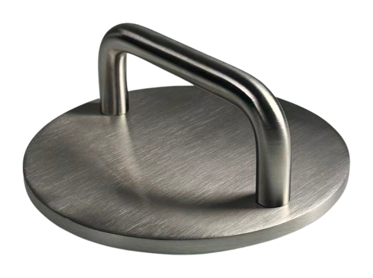
 盘古产品实物参考 · 步骤图为施工原理示意